« Zone of characterisation » : différence entre les versions
m (Eckert moved page Caracterization zone to Zone of characterisation) |
m (suppression du texte en français et remplacement de certaines figures par leur équivalent en anglais) |
||
| Ligne 13 : | Ligne 13 : | ||
- bottom contact/bottom gate (b)<br/> |
- bottom contact/bottom gate (b)<br/> |
||
- top contact/bottom gate (c)</p> |
- top contact/bottom gate (c)</p> |
||
| ⚫ | |||
<p>La mesure des caractéristiques de sortie et de transfert des transistors organiques à effet de champ est réalisée sous atmosphère inerte. Plusieurs configurations sont disponibles (Fig. 1):<br/> |
|||
| ⚫ | |||
- contact en bas/grille en haut ou "bottom contact/top gate" (a)<br/> |
|||
- contact en bas/grille en bas ou "bottom contact/bottom gate" (b)<br/> |
|||
- contact en haut/grille en bas ou "top contact/bottom gate" (c)</p> |
|||
| ⚫ | |||
| ⚫ | |||
Fig. 1 : Schéma des différentes configurations possibles pour les OFETs</center></p> |
|||
<p>The dimensions of the channel of the transistor are variable and depend on the chosen configuration. The channel is made either of a single compound (electron donor or acceptor) of the active layer of a photovoltaic cell (Fig. 2), or of a blend of electron donor and acceptor. Transfer characteristics are measured with a Keithley 4200 SCS system (Fig. 3). They allow the estimation of the mobility of the charge carriers by using the usual OFET's formalism.</p> |
<p>The dimensions of the channel of the transistor are variable and depend on the chosen configuration. The channel is made either of a single compound (electron donor or acceptor) of the active layer of a photovoltaic cell (Fig. 2), or of a blend of electron donor and acceptor. Transfer characteristics are measured with a Keithley 4200 SCS system (Fig. 3). They allow the estimation of the mobility of the charge carriers by using the usual OFET's formalism.</p> |
||
<p>Les dimensions du canal du transistor sont variables et dépendent de la configuration choisie. Le canal est constitué soit d’un seul composant (donneur ou accepteur d’électrons) de la couche active d’une cellule photovoltaïque (Fig. 2), soit d’un mélange donneur/accepteur d’électrons. Les caractéristiques de transfert mesurées à l’aide d’un analyseur Keithley 4200 SCS (Fig. 3) permettent d’estimer la mobilité des porteurs de charges en utilisant le formalisme habituel des OFETs.</p> |
|||
<table border="0" cellpadding="5" cellspacing="1" style="width:100%;"> |
<table border="0" cellpadding="5" cellspacing="1" style="width:100%;"> |
||
<tr><td>[[Image:OFETcanal.jpg|center|Channel of an OFET viewed with an optical microscope]]</td> |
<tr><td>[[Image:OFETcanal.jpg|center|Channel of an OFET viewed with an optical microscope]]</td> |
||
<td>[[Image: |
<td>[[Image:OFETcourbesEnRed.jpg|center|Output characteristics of an OFET]]</td></tr> |
||
<tr valign="top"><td align="center">Fig. 2: Channel of an OFET in configuration bottom contact/bottom gate viewed with an optical microscope. This channel is made of a small semiconducting molecule.</td> |
<tr valign="top"><td align="center">Fig. 2: Channel of an OFET in configuration bottom contact/bottom gate viewed with an optical microscope. This channel is made of a small semiconducting molecule.</td> |
||
<td>Fig. 3: Output characteristics of an OFET: I<sub>ds</sub> is the drain-source current, V<sub>ds</sub> the drain-source voltage and V<sub>g</sub> the gate voltage.</td></tr> |
<td>Fig. 3: Output characteristics of an OFET: I<sub>ds</sub> is the drain-source current, V<sub>ds</sub> the drain-source voltage and V<sub>g</sub> the gate voltage.</td></tr></table> |
||
<tr valign="top"><td align="center">Fig. 2 : Vue au microscope optique du canal d'un OFET en configuration "bottom contact/bottom gate". Ce canal est constitué d'une petite molécule semi-conductrice.</td> |
|||
<td>Fig. 3 : Caractéristiques de sortie de l'OFET : I<sub>ds</sub> est le courant drain-source, V<sub>ds</sub> la tension drain-source et V<sub>g</sub> la tension de grille.</td></tr></table> |
|||
<br/> |
<br/> |
||
<p>OFETs have various applications, of wich [[Chemical sensors|chemical sensors]].</p> |
<p>OFETs have various applications, of wich [[Chemical sensors|chemical sensors]].</p> |
||
<p>Les OFETs ont différentes applications, dont les [[Capteurs chimiques|capteurs chimiques]].</p> |
|||
<br/><br/> |
<br/><br/> |
||
==Space Charge Limited Current (SCLC) devices== |
==Space Charge Limited Current (SCLC) devices== |
||
<p>The measurement of the I(V) characteristics of a diode with a single type of carriers allows the estimation of the mobility of the charge carriers if the current is limited by the space charge. Thus, a SCLC device is a semiconducting layer sandwiched between two electrodes whose extracting work is chosen to inject only electrons or only holes. The choice of these electrodes depends on the boundary energy levels of the organic semiconductor under study (Fig. 4). Devices of several thicknesses are necessary to ensure that the current is effectively limited by the space charge and not by carrier injection (same dependence: I proportional to V<sup>2</sup> in in both cases). I(V) measurements (Fig. 5) are done under controlled atmosphere and the thickness of the active layer is ascertained by profilometry.</p> |
<p>The measurement of the I(V) characteristics of a diode with a single type of carriers allows the estimation of the mobility of the charge carriers if the current is limited by the space charge. Thus, a SCLC device is a semiconducting layer sandwiched between two electrodes whose extracting work is chosen to inject only electrons or only holes. The choice of these electrodes depends on the boundary energy levels of the organic semiconductor under study (Fig. 4). Devices of several thicknesses are necessary to ensure that the current is effectively limited by the space charge and not by carrier injection (same dependence: I proportional to V<sup>2</sup> in in both cases). I(V) measurements (Fig. 5) are done under controlled atmosphere and the thickness of the active layer is ascertained by profilometry.</p> |
||
<p>La mesure des caractéristiques I(V) d’une diode à un seul type de porteurs permet de remonter à la mobilité des porteurs de charges si le courant est limité par la charge d’espace. Un dispositif SCLC est donc une couche de semi-conducteur prise en sandwich entre deux électrodes dont le travail d’extraction est choisi pour injecter uniquement des électrons ou uniquement des trous. Le choix de ces électrodes dépend des niveaux énergétiques frontières du semi-conducteur organique étudié (Fig. 4). Plusieurs épaisseurs de dispositif sont nécessaires pour s’assurer que le courant est bien limité par la charge d’espace et non par l’injection des porteurs (même dépendance : I proportionnel à V<sup>2</sup> dans les deux cas). Les mesures I(V) (Fig. 5) sont effectuées en atmosphère contrôlée et l’épaisseur de la couche active est déterminée par profilométrie.</p> |
|||
<table border="0" cellpadding="5" cellspacing="1" style="width:100%;"> |
<table border="0" cellpadding="5" cellspacing="1" style="width:100%;"> |
||
<tr><td width="50%">[[Image: |
<tr><td width="50%">[[Image:SCLCdispositifsEn.jpg|center|400px|SCLC devices for the measurement of hole mobility]]</td> |
||
<td width="50%">[[Image:SCLCcourbesRed.jpg|center|I(V) curves measured for SCLC devices]]</td></tr> |
<td width="50%">[[Image:SCLCcourbesRed.jpg|center|I(V) curves measured for SCLC devices]]</td></tr> |
||
<tr valign="top"><td align="center">Fig. 4: SCLC devices for the measurement of hole mobility. HOMO (Highest Occupied Molecular Orbital) and LUMO (Lowest Unoccupied Molecular Orbital) are the boundary orbitals of the small molecule or of the semiconducting polymer.</td> |
<tr valign="top"><td align="center">Fig. 4: SCLC devices for the measurement of hole mobility. HOMO (Highest Occupied Molecular Orbital) and LUMO (Lowest Unoccupied Molecular Orbital) are the boundary orbitals of the small molecule or of the semiconducting polymer.</td> |
||
<td>Fig. 5: I(V) curves measured for SCLC devices whose active layer (two different thicknesses) is made of a small semiconducting molecule. The ohmic regime (I proportional to V) is observed at low voltage and the SCLC regime (I proportional to V<sup>2</sup>) at voltages higher than 0.1 V.</td> |
<td>Fig. 5: I(V) curves measured for SCLC devices whose active layer (two different thicknesses) is made of a small semiconducting molecule. The ohmic regime (I proportional to V) is observed at low voltage and the SCLC regime (I proportional to V<sup>2</sup>) at voltages higher than 0.1 V.</td></tr></table> |
||
<tr valign="top"><td align="center">Fig. 4 : Schéma des dispositifs SCLC pour la mesure de la mobilité des trous. HOMO (Highest Occupied Molecular Orbital) et LUMO (Lowest Unoccupied Molecular Orbital) sont les orbitales frontières de la petite molécule ou du polymère semi-conducteur.</td> |
|||
<td>Fig. 5 : Courbes I(V) mesurées sur des dispositifs SCLC dont la couche active (deux épaisseurs différentes) est constituée d’une petite molécule semi-conductrice. Le régime ohmique (I proportionnel à V) est observé aux faibles tensions et le régime SCLC (I proportionnel à V<sup>2</sup>) aux tensions supérieures à 0,1 V.</td></tr></table> |
|||
<br/> |
|||
Dernière version du 25 août 2016 à 07:20
 |
 | |
Head: Daniel MATHIOT, Contact |
Organic Field Effect Transistors (OFETs)
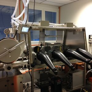
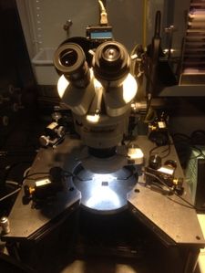
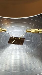
The measurement of the output and transfert caracteristics of organic field effect transistors is carried out under inert atmosphere. Several configurations are available (Fig. 1):
- bottom contact/top gate (a)
- bottom contact/bottom gate (b)
- top contact/bottom gate (c)

Fig. 1: Different configurations available for the OFETs
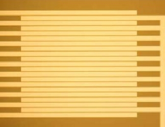
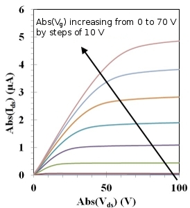
The dimensions of the channel of the transistor are variable and depend on the chosen configuration. The channel is made either of a single compound (electron donor or acceptor) of the active layer of a photovoltaic cell (Fig. 2), or of a blend of electron donor and acceptor. Transfer characteristics are measured with a Keithley 4200 SCS system (Fig. 3). They allow the estimation of the mobility of the charge carriers by using the usual OFET's formalism.
| Fig. 2: Channel of an OFET in configuration bottom contact/bottom gate viewed with an optical microscope. This channel is made of a small semiconducting molecule. | Fig. 3: Output characteristics of an OFET: Ids is the drain-source current, Vds the drain-source voltage and Vg the gate voltage. |
OFETs have various applications, of wich chemical sensors.
Space Charge Limited Current (SCLC) devices
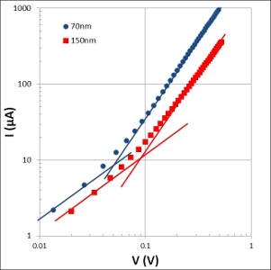
The measurement of the I(V) characteristics of a diode with a single type of carriers allows the estimation of the mobility of the charge carriers if the current is limited by the space charge. Thus, a SCLC device is a semiconducting layer sandwiched between two electrodes whose extracting work is chosen to inject only electrons or only holes. The choice of these electrodes depends on the boundary energy levels of the organic semiconductor under study (Fig. 4). Devices of several thicknesses are necessary to ensure that the current is effectively limited by the space charge and not by carrier injection (same dependence: I proportional to V2 in in both cases). I(V) measurements (Fig. 5) are done under controlled atmosphere and the thickness of the active layer is ascertained by profilometry.
| Fig. 4: SCLC devices for the measurement of hole mobility. HOMO (Highest Occupied Molecular Orbital) and LUMO (Lowest Unoccupied Molecular Orbital) are the boundary orbitals of the small molecule or of the semiconducting polymer. | Fig. 5: I(V) curves measured for SCLC devices whose active layer (two different thicknesses) is made of a small semiconducting molecule. The ohmic regime (I proportional to V) is observed at low voltage and the SCLC regime (I proportional to V2) at voltages higher than 0.1 V. |


